Rock Shear Box Apparatus
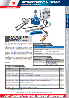
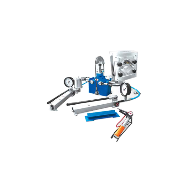
- This shear box has been designed to receive irregularly shaped samples with surfaces measuring up to 115 x 125 mm or cores with a maximum diameter of 102 mm.
- The lower half of the box is connected to two hydraulic rams which generate the shearing force (in both directions) and the upper half supports the ram that applies the load at a right angle to the failure surface.
- The horizontal and vertical actuators are connected to two manually-operated hydraulic pumps.
- During the test the normal stress and the shearing stress are read on two independent dial gauges calibrated in engineering units; if the measurement of the shear deformation is required an appropriate dial gauge can be mounted on the support.
Category : Aggregate & Rock Testing Equipments
Code : NL 1030 X / 001
Description
Technical Specifications
| Standard | ASTM D5607, ISRM |
| Maximum Capacity | 50 kN |
| Dimension | 770 (L) x 220 (W) x 590 (H) mm |
| Approx. Weight | 60 kg |
Unit Consists Of
| Model Number | Parts Description | Qty |
| NL 1030 X / 001 – P 001 | Mould Former | 1no. |
| NL 1030 X / 001 – P 002 | Pressure Maintainer Set | 1set |
| NL 1030 X / 001 – P 003 | Sample Casting Plaster (25 kg / pack) | 1bag |
| NL 1030 X / 001 – P 004 | Manual Hand Pump c/w House & Quick Coupling (Female) | 2nos |
| NL 1030 X / 001 – P 005 | Horizontal Shearing Unit with 2 Rams (1 In Each Direction) | 1set |
| NL 1030 X / 001 – P 006 | Vertical Force Ram Unit | 1no. |
| NL 1030 X / 001 – P 007 | 50kN x 1kN Pressure Gauge c/w Quick Coupling (Male) | 2nos. |
| NL 7020 X / 006 | Dial Indicator 25 mm x 0.01 mm | 1no. |
Optional Accessories :
| Model Number | Accessories Description |
| NL 1030 X / 001 – A 001 | Vertical Displacement Tools Set: Mounting Bracket |
| NL 7020 X / 007 | Digital Dial Indicator 12.7 mm x 0.001 mm |
For detailed specifications refer to the Product Brochure.
NL Scientific
Rock Shear Box Apparatus
This shear box has been designed to receive irregularly shaped samples with surfaces measuring up to 115 x 125 mm or cores with a maximum diameter of 102 mm. The lower half of the box is connected to two hydraulic rams which generate the shearing force (in both directions) and the upper half supports the ram that applies the load at a right angle to the failure surface. The horizontal and vertical actuators are connected to two manually-operated hydraulic pumps. During the test the normal stress and the shearing stress are read on two independent dial gauges calibrated in engineering units; if the measurement of the shear deformation is required an appropriate dial gauge can be mounted on the support.

 Shop
Shop